-
- QLight
- Boxco
- i-Bon
- Brother
- ID Printer
- M.I.E
- Upun
- i-Wire
- S-Switch
- World Tech
-
Switchwell
- Single Output Switching Power Supply
- Dual Output Switching Power Supply
- Triple Output Switching Power Supply
- Single Output With Battery Changer
- Din-Rail Power Supply
- 1U Standard Power Supply
- CE Approved Power Supply
- Power Supply with PFC Supply
- Open-Frame Power Supply
- U-bracket Power Supply
- LCD Inverter Supply
- LED driver Supply
- Single Output Adapter
- Senor
- Arbor
- Carlo Gavazzi
- Highlighted Products
Notice: Undefined index: debug in /home/sclsystem/public_html/cache/smarty/compile/fc/b6/55/fcb6553ca490786cc4cad67dd2cf5ad53a945277.file.category.tpl.php on line 39
DuplineSafe There are 12 products.
-
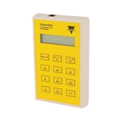
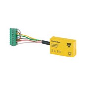
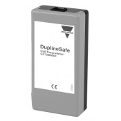
DuplineSafe Configuration & Test Unit
Configuration and Test Unit for DuplineSafe. Configures DuplineSafe Safety Relay Output module type number GS38300143230 and DuplineSafe Safety Input module type number GS75102101. Monitors the DuplineSafe bus in Test Unit mode. Highly recommended for DuplineSafe system startup, troubleshooting and maintenance. GET A QUOTE
-
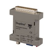
Dupline Modbus Interface Module with...
GSTI50 is originally designed as an interface solution for Dupline® GTD50 display, but can be used by all other Modbus-RTU masters. The GSTI50 supports Modbus- RTU function code "3" (read registers) and function code "16" (write registers), and can read/write all 128 Dupline® I/O’s. The maximum numbers of registers that are allowed in 1...
-
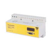
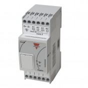
Dupline Profibus-DP Gateway Passive with...
Dupline® Gateway with the function of a PROFIBUS-DP slave. This means that the Dupline® I/O’s (incl. Dupline® Safe signals) can be read/ controlled by PROFIBUS-DP masters (PLC’s, PC interface cards, etc. from various suppliers). Several Dupline® gateways can be connected to the same Dupline® network. The unit is certified...
-
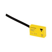
GS 7510 2101 Safety Input Module
Bus-powered safety input module approved according to IEC/EN 61508-SIL3, IEC/EN 62061-SIL3 and ISO/EN 13849-1 PL e by TÜV. The module has a single input for potential-free contacts, and it uses two Dupline® channels for sending the safety signal. The small dimension IP67 housing makes it suitable for de-central installation, e.g. inside a...
-
GS 7510 2101-1 Safety Input Module
Bus-powered safety input module approved according to IEC/EN 61508-SIL3, IEC/EN 62061-SIL3 and ISO/EN 13849-1 PL e by TÜV. The module has a single input for potential-free contacts, and it uses two Dupline® channels for sending the safety signal. The small dimension IP67 housing makes it suitable for decentral installation, e.g. inside a...
-
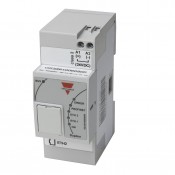
Dupline Master Channel Generator
The Master channel generator GS3390 0000 800 provides the channel generator output drive for one Dupline® network. Up to 7 Master Channel Generators can be connected to one profinet gateway GS3391 0060 800. By using the dipswitches on the front, the user can select ID addresses and change between the different modes explained below in the datasheet....
-
Dupline Master Channel Generator
The Master channel generator GS33900000800A provides the channel generator output drive for one Dupline® network. Up to 7 Master Channel Generators can be connected to one profinet gateway GS33910060 800 By using the dip switches on the front, the user can select ID addresses and change between the different modes explained below in the datasheet....
-
Dupline Profinet Gateway
The GS33910060800 is a Profinet gateway with a built-in 2-port switch. The module has no settings and works only in association with the master generator GS3390 0000 800. By installing the GSD file in the PLC, the installer can design the functionallity of e.g. digital in/out, analink, mux BCD and Dupline® safe signals. After installation and...
-
DuplineSafe Optical Fibre Converter
The GS34930000 converts the Dupline® signal for transmission on optical multimode fibre pairs (50/125, 62.5/125). The GS34930000 always operates together with a GS34920000, which converts the signal back from optical to electrical representation via a built-in channel generator output stage. Up to 5 km optical transmission distance can be achieved....
-
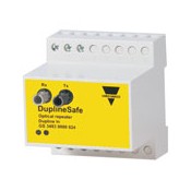
DuplineSafe Repeater
The Dupline® Repeater is used to increase the distance in a standard Dupline® network, and a Dupline® network with safety modules. Furthermore, it can be used as a “Power-booster” in sections with several Dupline®-supplied units. GET A QUOTE
-
DuplineSafe Configuration Programmer
Configuration unit for DuplineSafe products. Configures DuplineSafe safety relay Output module type number GS38300143230 and DuplineSafe Safety Input module type number GS75102101x. The configuration settings can be saved and printed. GET A QUOTE
-
DuplineSafe Relay Output Module
DuplineSafe relay output module approved according to IEC/EN 61508-SIL3, IEC/ EN 62061-SIL3 and ISO/EN 13849-1 PL e by TÜV. The module monitors up to 63 DuplineSafe input modules, type number GS751021xx. The NO relay contacts are only in the closed position if a valid “safe state” signal is received from all the Safety Input modules...

